N64 Multinorm single switch mod & overclocking
This is a schematic how to build a multinorm N64 with just a single switch.
It is based on the information provided from d4s. Without him this mod wouldn´t be possible!
What you need for Multinorm mod:
- Pal N64 console
- NTSC Console with RGB mod (otherwise you may get a black & white screen)
- 1 IC MC14551B (Multiplexer chip)
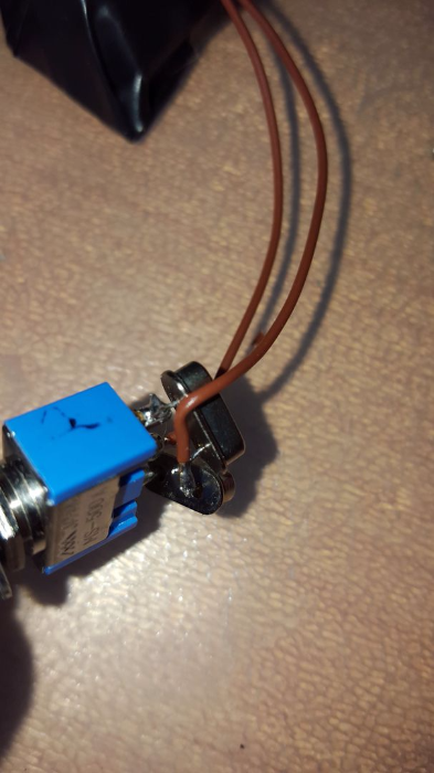
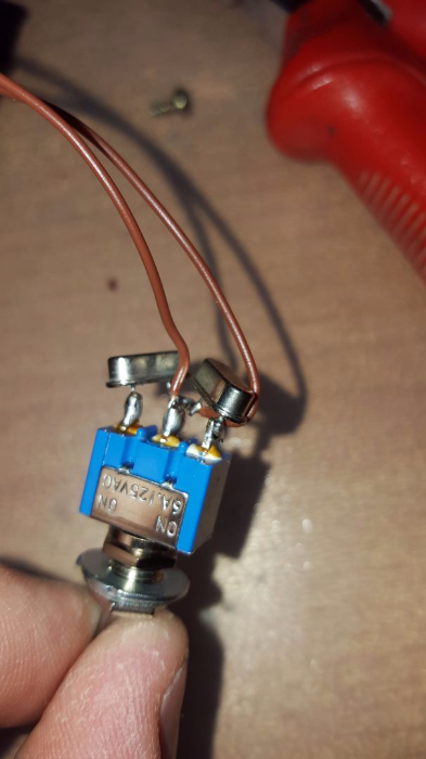
- 1 single pole, triple throw switch (ON-OFF-ON)
for overclocking:
- 1 single pole switch (ON/ON)
This mod is for experienced users! Wrong wirering can destroy the console.
First you have to desolder the PIF(P)-NUS chip from the Pal console.
From the NTSC console you have to lift pins 2,5,6,8,10,12,14 and 28 from the PIF-NUS chip.
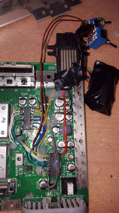
Get a perfboard and solder the IC MC14551B to it. Then begin soldering wires from the PCB as shown on my schematic to the corresponding pins on the IC. This is the hardest and trickiest part to do. Be carefull to not destroy the contact pins of your pcb!
Then also lift pins 2,5,6,8,10,12,14 and 28 from the PIF(P)-NUS chip and piggyback the chip on top of the PIF-NUS chip. Connect all left pins from the PIF-NUS and PIF(P)-NUS chips together.
Then wire all lifted pins according to my schematic and it should work.
For your information:
Pin 28 of the PCB is 3.3V and 10,12 and 14 are GND.
Pal cartridges will not pop in the NTSC console slot. The slot needs to be modified. You can cut it out (and leave holes) or use a soldering iron to melt the plastic on the neccessary places and close the gaps.
If you want to overclock your N64:
Desolder crystal X1 D177.. of your Pal console and crystal X1 D143.. of your NTSC console.
Connect one leg of the D177 crystal with one leg of the D143 crystal. The other legs go the left and to the right site of the switch.
Solder 2 wires on the 2 X1 connection points.
Connect one wire end to the middle joint of the single pole ON/ON switch and the other wire end to connection point of D177 and D143.
Do this at your own risk.
Site note:
It´s not possible to force 50Hz or 60Hz Mode. 50Hz or 60Hz is selected by the game cartridge itself (CIC chip inside).


1. Video: First try with multiple switches as described in the original schematic by d4s
2. Video: Final mod with one switch with modified schematic from me